
Or: How to add a XLR-connector to the RB 500 ribbon microphone
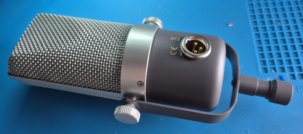
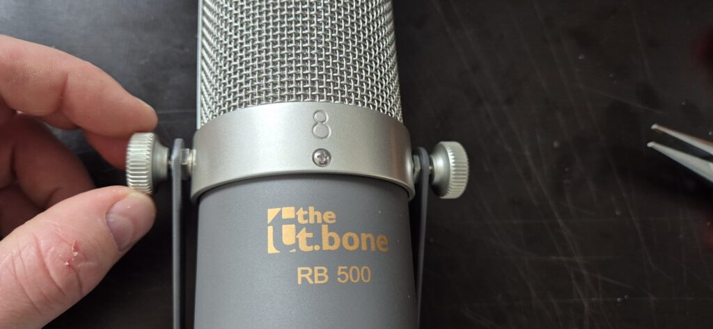
The RB-500 is a ribbon microphone by the Thomann house-brand the t.bone and is an extremely good deal if you care for getting a decent ribbon microphone especially if you consider the low price (at time of writing: 99 Euros). The mic has a ribbon-typical dark sound, meaning the high end rolls off early and a pronounced proximity effect with which you can essentially increase the bass response of a source as you get closer to the mic. Should you need high frequency you can still EQ it back in, which sounds quite nice. The mic feels sturdy and has a solid steel mount.
One aspect of the mic that feels a little annoying is the cable that has been attached to the mic body in a non-removeable manner. In this article I describe how I modded the mic in such way you can connect directly to the mic with an XLR cable.
The Plan
To add a XLR connector we follow these steps: disassemble the microphone, remove the old cable with the strain relieve, drill a hole into the cup, solder a shielded cable to the XLR connector, mount a XLR connector into the hole, solder it to the microphone PCB and then reassemble the microphone.
Before we proceed, one warning:
WARNING: I successfully performed this mod not only once, but twice. Nothing in this guide is fancy rocket-science, but nearly every step depends on the skills of the person doing it.
Since I can’t judge the skill level of anonymous strangers on the internet, if you have any doubt, please keep the mic as it is. If you proceed anyways and end up with a broken microphone: you have been warned!
With that out of the way – if you don’t have two left hands, know how to use a drill and solder, this should be entirely possible. And if you don’t know how to use a drill and solder, consider to get some practise before attempting this.
Needed PartS
In fact we just need one part and that is the XLR-connector. Since we want to add a XLR-connector to a cylindrical case not every type of XLR-connector will work. The usual D-norm connectors made by the likes of Neutrik and Amphenol for example will be very hard to mount.
Luckily there are also other connectors out there, I took the Neutrik NC3 MPR-HD. At time of writing this connector costs 12,20 € at Thomann Germany which isn’t exactly cheap for a single connector, but maybe you find something cheaper. If you do, please ensure to measure the correct drilling diameter 1.
Needed Tools
Except for the soldering iron, the step drill may be the thing that you might not just have lying around. This is a type of christmas-tree-shaped drill that allows you to cut very nice looking big holes into sheet metal2. These don’t come cheap, but last long and replace multiple drills at once, so definitely worth it.
Another way to get a 20mm hole would be a 20mm hole punch, but since we have a cylindrically curved surface here that hole punch may actually deform the body, so drilling is preferential.
Yet another way would be to draw the circle onto the cup and widen the existing hole with some other tool like a round metal file.
Obviously, since we drill a hole this mod isn’t easily reversible. As the mic isn’t that expensive that is probably acceptable.
What is needed
- Screwdriver (Small Philips)
- Pliers
- Pliers (needle nose)
- Side Cutter
- Bench drill or chorded drill
- Drilling bit for 20mm diameter holes
- Soldering iron and solder
- Sharp knife
- (helpful) soft cloth
- (helpful) cutting oil
- (helpful) alcohol for cleaning
- (helpful) vice to hold the cup while drilling
Instructions
⚠ please read the instructions fully, before you start following it!
Before you start doing anything make sure you have everything (tools, parts, space) that is needed. If you want a nice looking result clear some room and make sure your working surfaces are clean and free of any clutter that could scratch the microphone. Consider it an option to wrap something soft around the mic while you work on it. The biggest risk for your mic will be that you drop it on the floor. The best way to mitigate that risk is to never put it anywhere where it could roll of the table.
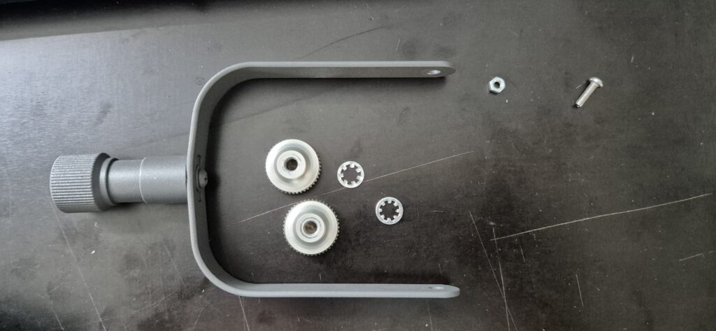
Step 1: Disassembly
Before we can add the new connector we need to first disassemble the microphone, so we can remove the existing cable in the next step. Please note that these instructions do not contain the re-assembly part, as my assumption here is, that anybody who manages the disassembly will be able to reassemble the mic as well. If you have trouble with the reassembly just go through the steps in reverse and carefully look at the pictures.
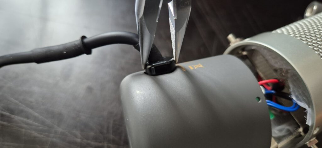
Step 2: Cable Removal
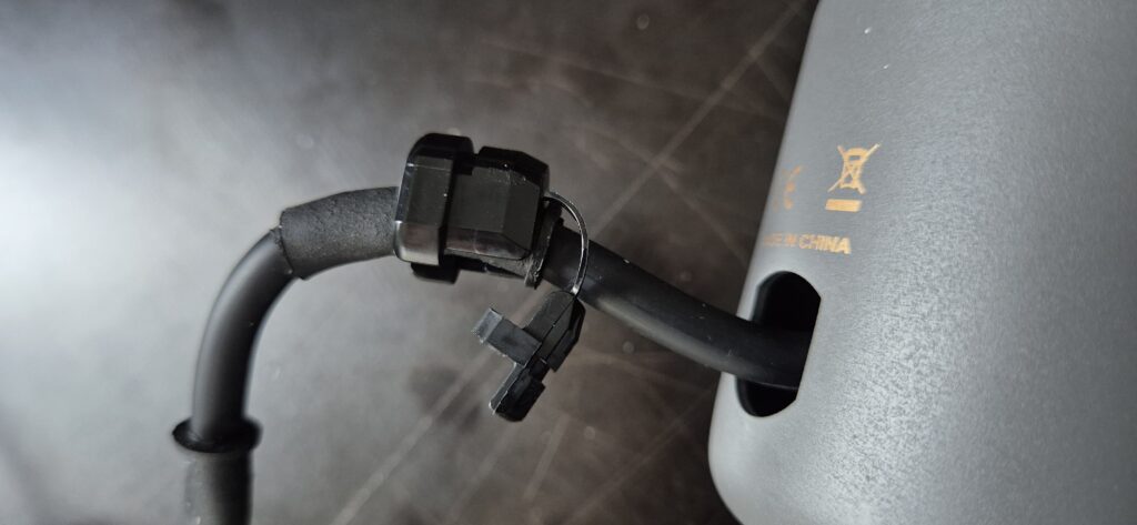
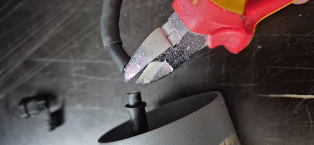
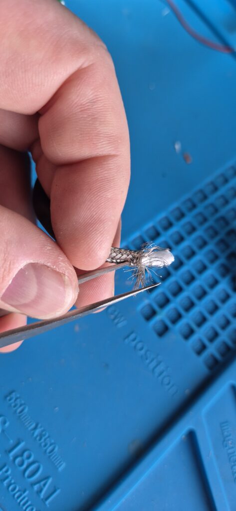
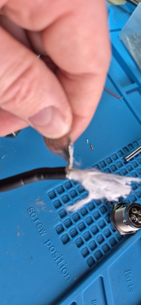
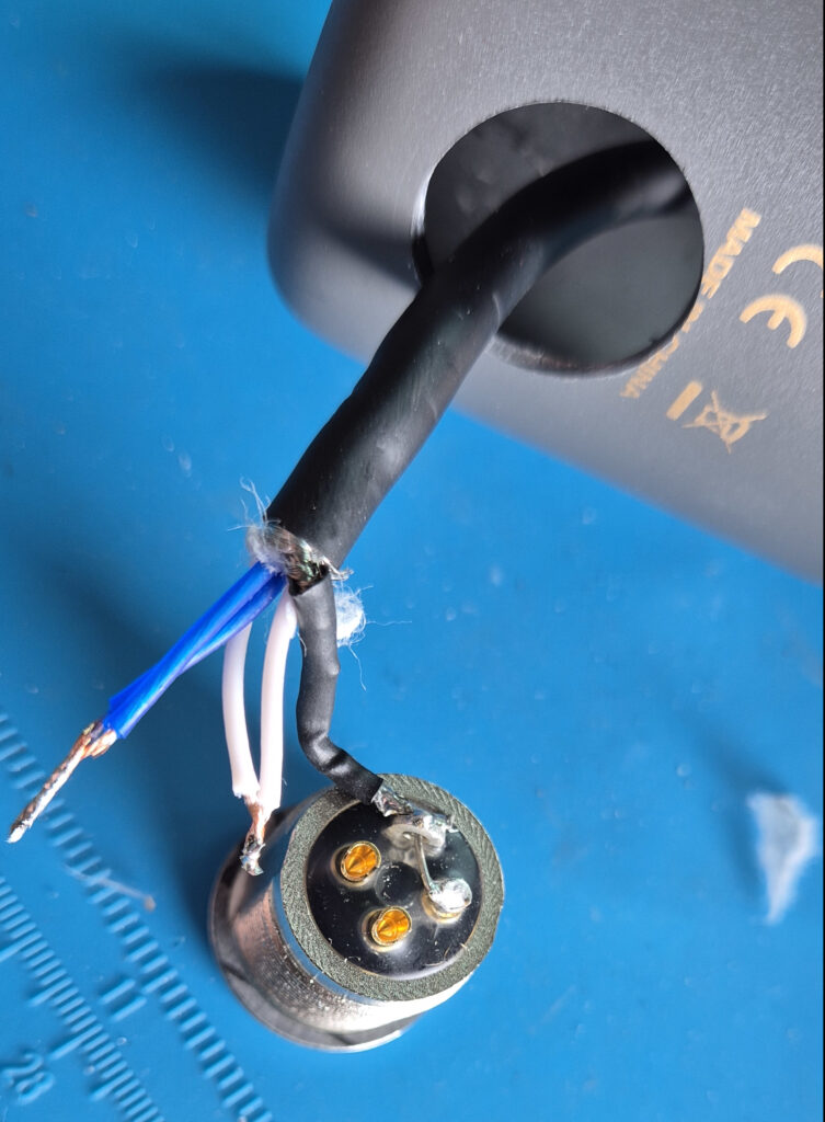
Now that the mic is opened, we proceed to remove the cable. We are going to keep a small length of the original cable around which will be later soldered to the new XLR connector. To remove the cable we first need to remove the strain relief (the part that protects the PCB from the cable pull).
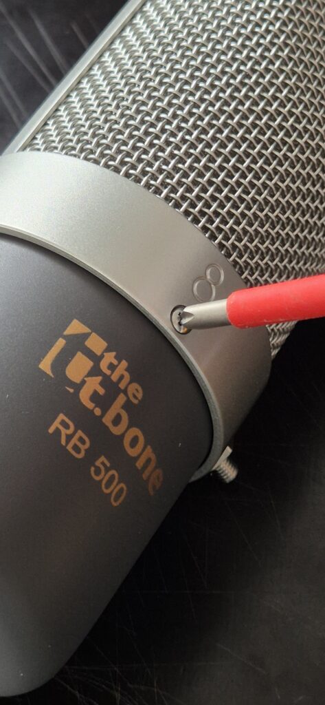
Part 3: Drilling Holes
In order to add a new connector we need to make space for it in the body (“cup”) of the microphone. The original hole for the strain relief isn’t round and way too small for a XLR-connector, so the goal is to make a bigger hole.
How you reach that goal depends a bit on your metal working skills and the tools available to you. The cup consists of 2mm strong steel which isn’t the most friendly to machine and since the cup is cylindrical using a hole punch might deform the cup.
Since I have a bench drill and a stepped drill that is perfectly suited for cutting a 20mm hole into a 2mm steel sheet, I went that route. If you have no such thing drilling smaller holes and then using a round metal file with some patience would also work.
Note: If you go the drilling route you might wanna use some cutting oil for a cleaner cut and a longer lifespan of the drill.
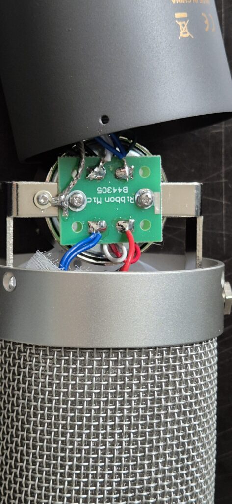
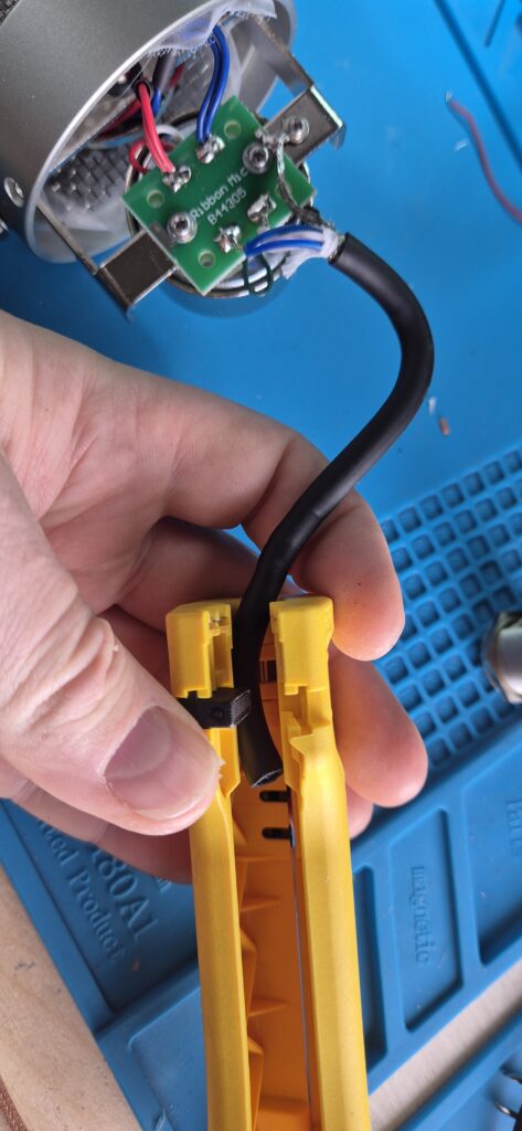
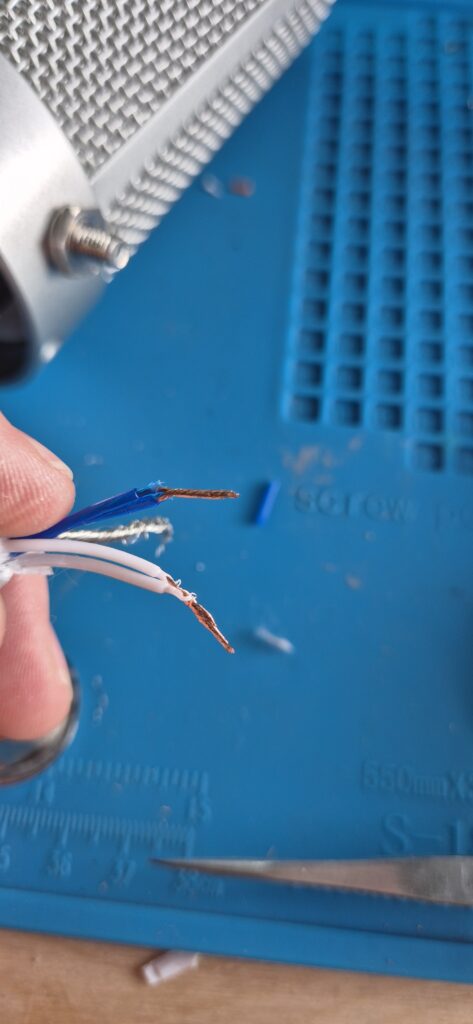
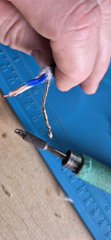
Part 4: Electrical Connections
Now everything is prepared to make the final electrical connections. I assume you know how to solder cables. If you don’t this is the time to go and watch some tutorial videos.


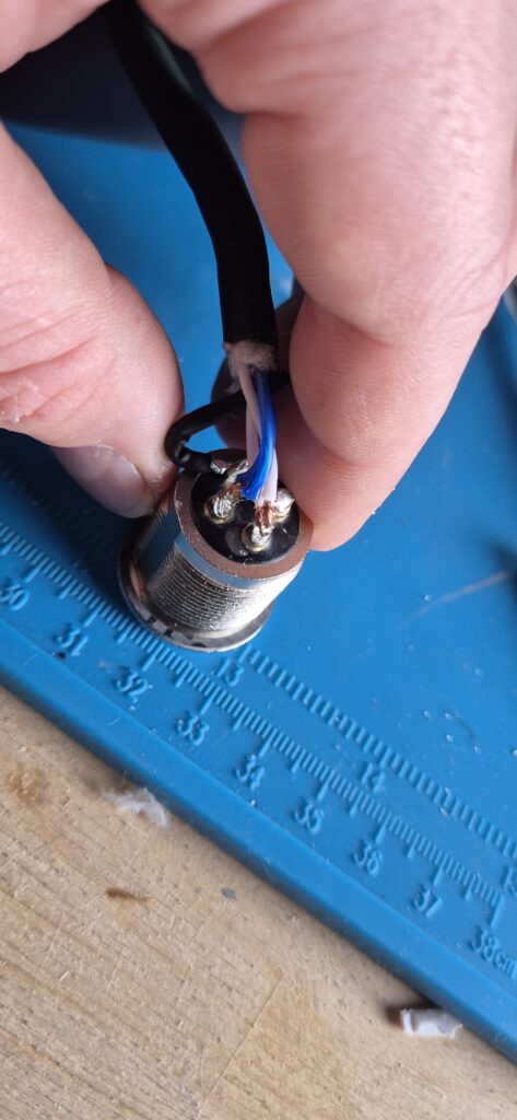
Step 5: Solder the connector
With the cables prepared we can move on to soldering the XLR connector.
⚠ BEFORE you solder to the connector you need to pull the cable through the XLR-connectors nut AND through the drilled hole from inside the cup. If you miss this step you will need to desolder.

Step 6: Testing
Now with all electrical connections made the next step would be assembly one would think. However you could also imagine that now is the ideal time to test the new connector, because if something doesn’t work you don’t need to disassemble everything again.
To test the mic just connect it to a suitable microphone input (as a precaution without phantom power active) an see if something comes out.
If it does not work you should check your solder connections. Are they all where they should be? Are there no additional connections (short circuits!) between the pins? If you can answer all these questions with yes, it should work.
Final Step: Assembly
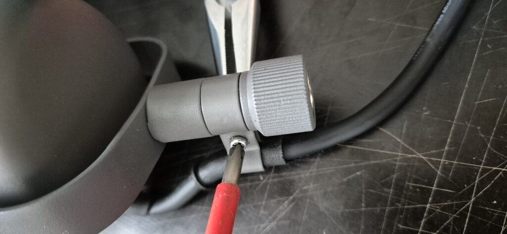
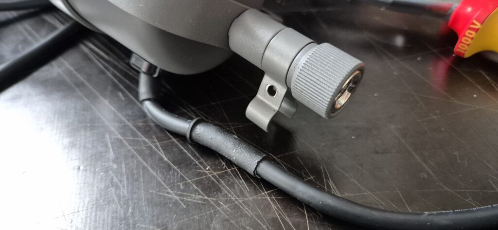
As we now know the mic works, we can re-assemble the mic. First we need to fix the connector nut.
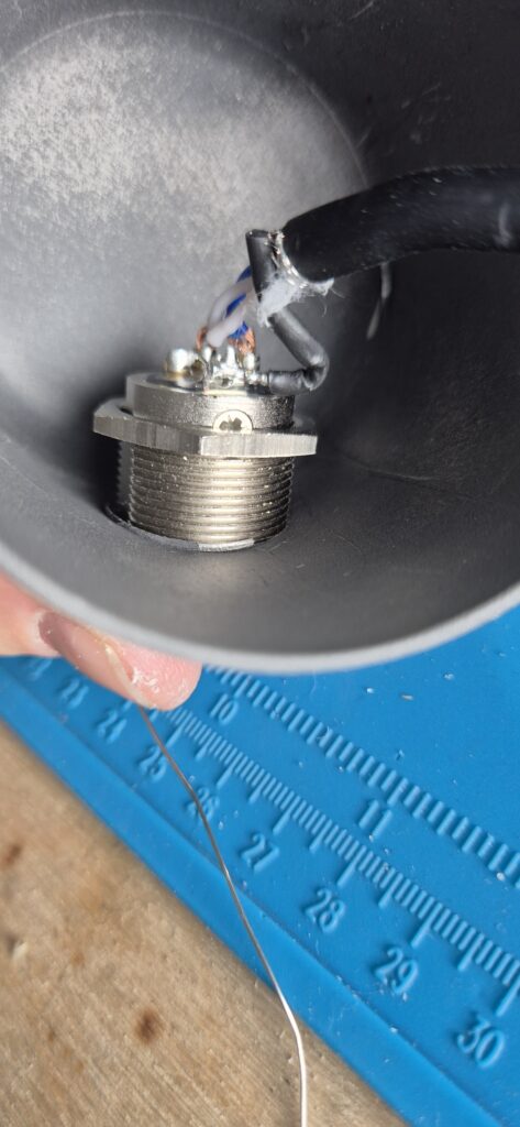
This isn’t an ideal screw connection, since the inside of the cup is curved, but it can work out well in practise. You can add some glue from a hot-melt gun to fix it in place even better.
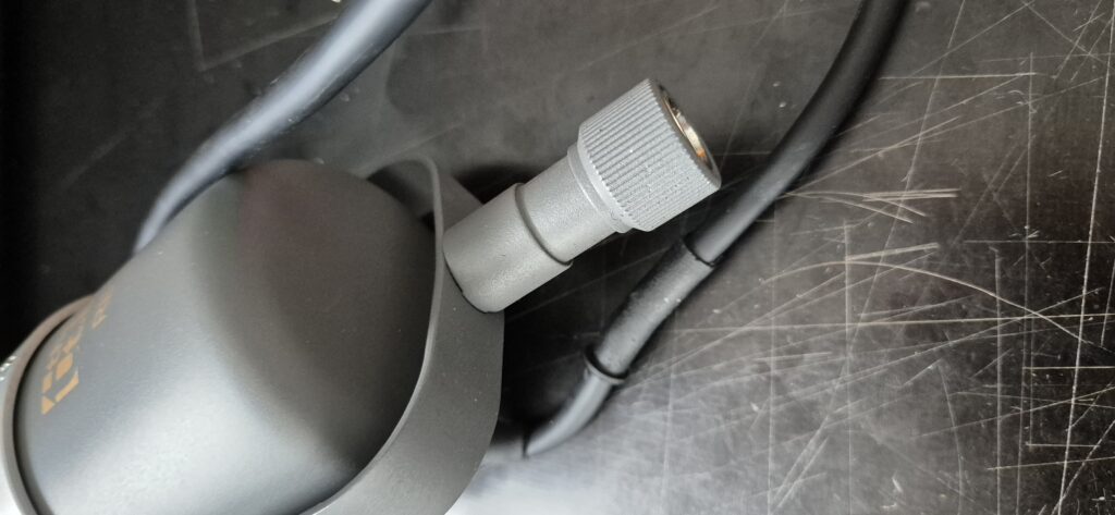
After this the reassembly is basically just what you did in Step 1 (Fig.5 to Fig.8) in reverse. If you made it this far I have no doubt you can manage this without the pictures.
Below you can see two of my RB 500 mics in action. They are mounted in a Mid-Side (M/S) configuration3. Since the RB 500 has a polar pickup pattern of Figure 8, you can use two mics to produce a stereo recording. In my case the top mic records the mid (so everything from the front and from the back) and the bottom mic records the sides (left and right). This works wonderfully well in front of a drum kit.
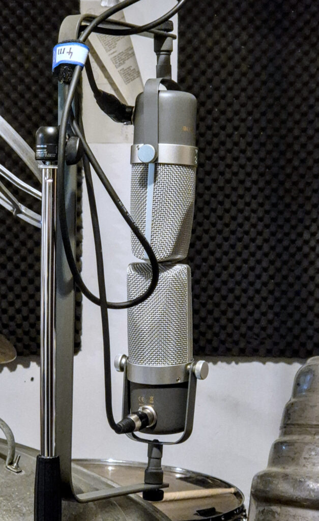
If you wonder about the C-bracket: I basically just bent a piece of flatbar-iron myself, drilled two holes and mounted it using the suitable microphone screws.
As you can See I also use the mics with angled and non-angled XLR-plugs, this allows me to not have the cable hanging in front of the mic.
- I measured a diameter of 20mm for the NC3 MPR-HD connector[↩]
- The step drill is also called a Unidrill. See Wikipedia for details[↩]
- Mid-Side stereophonic recordings can be converted to Left-Right stereophonic recordings and vice versa. See also: Wikipedia[↩]
Leave a Reply